Conclusion of NASA Robot Project

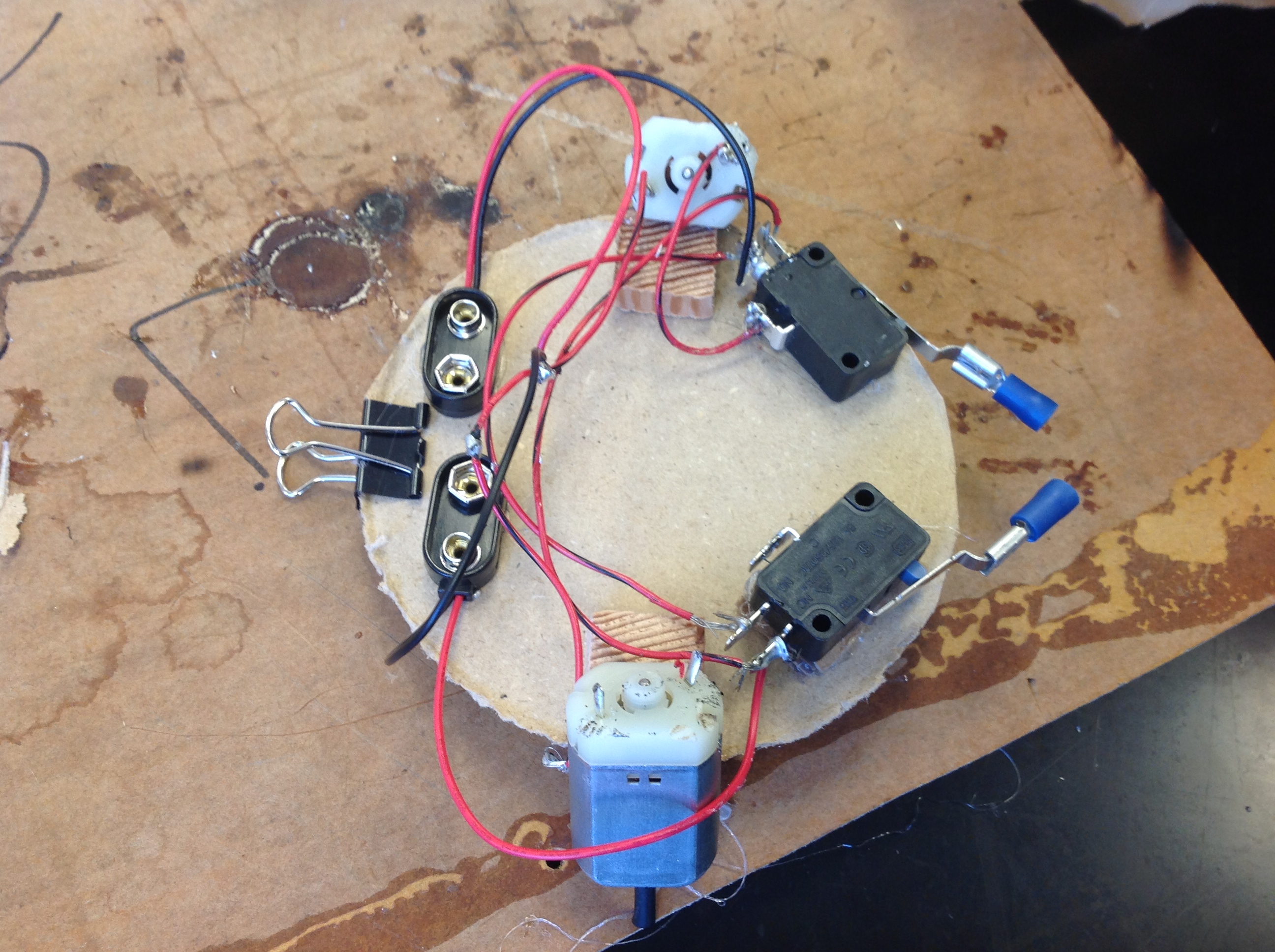
The main successes and failures of our project was the wiring. There were some wires where they would go to a different spot on each switch, but they would start at the same spot on each motor. This really confused me mainly, and because of that, we had to melt the solder on each of those spots. This was annoying, but it taught me and my partner how to problem solve when we messed up.

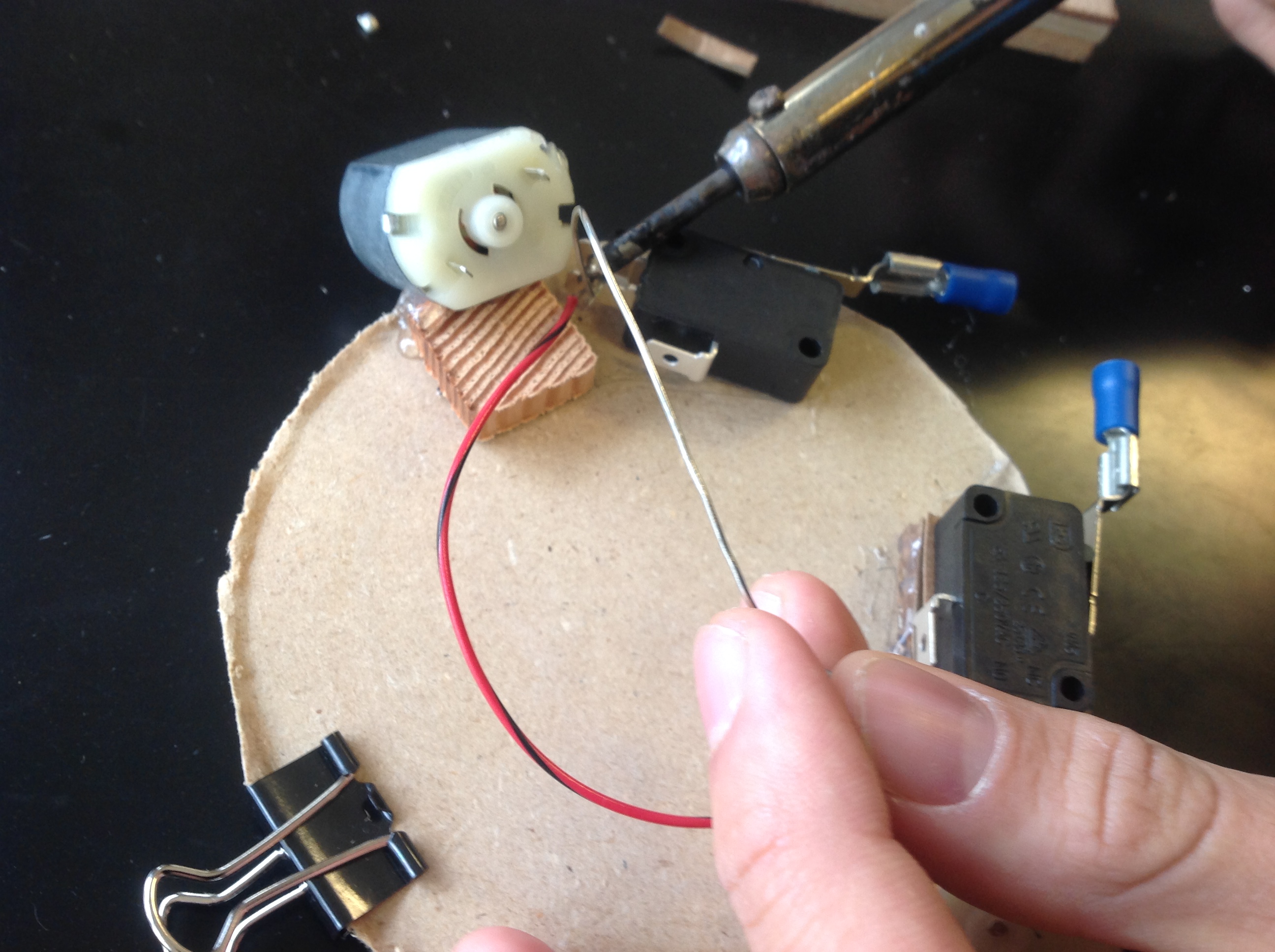
I learned a lot throughout this project. I learned how to solder, and how electrical motors and currents work. I think this was defiantly a fun project, because I learned important skills and understanding of how electricity works and transfers from batteries to different parts of a robot.

If I were to do something differently next time, I think I would look at the diagram more closely. That was my major flaw, because I did not look closely enough at the diagram. It caused us to have to make multiple wiring re makes, which, though it isn’t bad, it was annoying to some extent.

The parts I liked about this project were almost everything. I loved being able to work with my friends, have fun, and build a unmanned robot. If there was one thing I could change, I would probably want to be a 3 person group with one of my other friends, or maybe build a more complex robot. Other than those things, it was a great, fun project to do!


Documentation of NASA Robot Project

In this post, I will explain the different documented steps of our project that my partner and I took to create this incredible robot.Image


At this stage(above), the robot was nothing but a mere skeleton. All we had done is glue the motors onto the body, as well as a third wheel mechanism, which is otherwise know as a file clip.

Image

In this image, my partner and I are using a heat gun to melt the shrink rap around the motor shafts, so that they will get traction on the floor.

Image


As seen in this image above, we have now added the switches, that when the robot is complete, will serve one of the most important features: switching the motor and robot direction when the robot runs into a wall. These switches, where activated, will reverse the motors, so it doesn’t continuously go straight.Image

This next photo is the image us soldering the first of the wires onto the motor and switch. These wires will transit the electrical circuits from the batteries and into the motors to power them.

Image


With the wires complete and the battery connectors glued in, we are ready for testing! If I recall correctly, we had a couple wiring issues we needed to fix, but this a basic look at the complete wiring of our NASA Robot Project Robot.

Intro to NASA Robot Lab

Our most recent lab in Integrated Science was to create a robot that would move through a simple maze, without us controlling it. The maze was a couple simple turns, with the robot using bumpers and switches to turn when it hit the wall. This will be explained more in-depth later on in the post. We would go on through trouble and errors to create a working robot that completed the course in 11.48 seconds, the 2nd fastest time in our class, and the 8th fastest in all of the classes.

We believe that we were assigned this project because it is different, and a valuable learning opportunity. Especially in the world we are growing up in, knowing how to use electronics and stuff in that area is very important, and can lead to great opportunities in life. I also think we did this project because it’s different. Most science classes would just do simple posters and projects, but because of the opportunities we get, we can do something more interesting, more intriguing, and overall it is better.

We used many scientific concepts throughout the project. These included switches, friction, batteries, balance, continuous circuits and many more. The only way for the robot to turn would be with switches, which were on the ends of the robot. When a switch was activated, which would happen when the robot hits wall, it would activate the other battery/motor to turn backwards and reverse directions. The wheels that we used on our robot where the shafts of the motor. But, there is no way to get good traction with metal on a hard marble floor. What we did to counter this was attach tires to the edge, which was shrink wrap. This allowed for easy movement along the floor. The reason the robot was able to work was because of basic wiring. This caused the robot to turn when the switches were pressed, and more in detail, it would switch the polarity and as long as the switch was pressed, the motor would go in reverse, causing the robot to turn away from the wall. The last main aspect of the robot was the balance. We had one motor on either side but that wouldn’t balance it enough. So, to help balance it, we put a small clip hanging off the end,that created a “third” wheel.

Conclusion of Labs

I learned a lot in these labs. Most of it is pretty simple, but it’s stuff I did not know. It took me and my partner a good 5 minutes to figure out how to connect the battery+light bulb+wires, but now that I know how, it can be used for so many things in the electrical area in life. The electric motor lab was very fun. Trying to figure out how to connect up the motor and battery, then learning about the poles from magnetism. I would definitely recommend this lab in the future. It was fun, interesting and a good lab experiment overall. The walkie talkie and speaker were very fun labs, to learn how sound travels through something as simple as string and a cup, as well as the speaker to a extent. They both worked similarly, and were equally fun and enjoying. I am not sure if there are many real life applications to the speaker/cup phone, but in a way, it gives you a clear example of how sound travels through certain objects.

 All in all, I would defiantly recommend this lab in the future. I learned a lot from it, and found it very fun.  

Cup Speaker Lab

The 4th and final lab we made in Science class was the Cup Speaker. Our teacher played a CD through a speaker, and after tampering with the wiring, we connected multiple sets of alligator clips/wires that were connected to copper wire, which was wrapped around a magnet on a paper cup. There are 2 magnets, one on the top and one on the bottom end of the cup. The sound then travels through the wires via the radio, onto the connecter, which leads to the coil vibrating, and the cup vibrating. After that, you hear the music through the cup. The image shown is the connection via the cords to cup!Image I learned that it is possible to transfer sound through this device in such a way, and that it comes out in such a clear quality.

Walkie-Talkie Lab

The 3rd lab we did in Science class was using the cup-phone method. We figured out how to create the cup-phone(walkie talkie) with just a paper cup and string.  The science behind this lab is very, very simple.

1. The person who is speaking’s vocal cords begin to vibrate.

2. Air in the speakers mouth vibrates

3. Air in speakers cup vibrates

4. Speakers cup vibrates

5. String vibrates

6. Receiving cup vibrates

7. Air in receiving cup vibrates

8. Eardrum of receiver vibrates

9. Receiver hears the sound sent through the wire

I could go into more detail about what happens through the brain that causes you to recognize and understand the simple vibrations, but for the purpose here, that is the basic process of a cup-phone/walkie talkie.Image

Electric Motor Lab

Our next science lab was to create electric motor. We were given some copper wire, 2 permenent magnets, a paper cup, a battery, 2 alligator wires, and 2 paper clips. The first step of this was put the magnets on the upside down cup. Then, we created the spoil of copper wire, and let it sit in between the 2 paper clips. From there, we attached the wires to the paper clips and battery, and now we have a complete circuit. The wires was now energized(via battery and paper clips), but it needed something to start it. We gave the wire a flick, and it started spinning. It would spin until the battery runs out. It is spinning because of the poles from the magnets. As the wire continues to spin, the magnetic poles flip and repel the wire, causing the spinning to occur. This continues until the battery runs out.

Basic Bulb, Battery, Wires, and Circuits

In science class, we created a full circuit that contained a light bulb, battery, alligator clips, and the circuit. After a few tries, we figured out that you had to connect the ends of the alligator wires to the bulb holder and to the battery, and that would create a complete circuit and turn on the light, as shown in the image below. When the wires become electrified, it creates a magnetic field around the wires.  I learned how to create a full circuit, something I did not think of before. This was a very  fun and interesting  lab. More cool stuff to come!photo 3 - Copy